This post is not meant to be an introduction to traceroute in MPLS. There are many good resources on this topic already.
It is meant to provide a quick reference how a traceroute should look like in a healthy network and how different features might influence the outputs. Most of articles I’ve seen neglect these aspects. In all scenarios we have TTL-propagation enabled.
Specifically, we will look how traceroute output is altered when we play with:
- unicast RPF
- label allocation modes
- ACLs
The reason I feel this is important is that not fully understanding the process might lead us to wrong conclusions during troubleshooting process.
DISCLAIMER:
This article is based on my own experience and lab testing performed on real hardware. I did my best to ensure that below information is accurate, however, I’m not a TAC engineer so I have to assume certain facts about lookup process when using different label allocation modes. If you feel that something needs correction please make a comment.
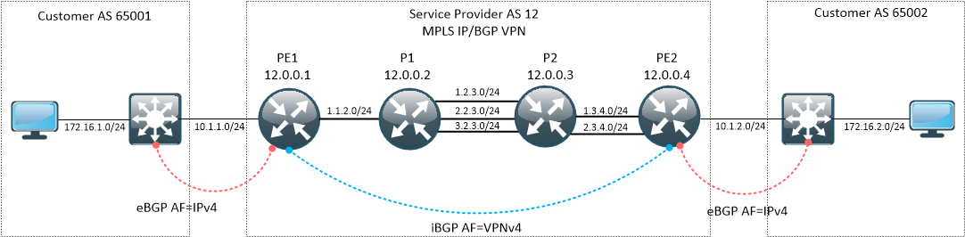
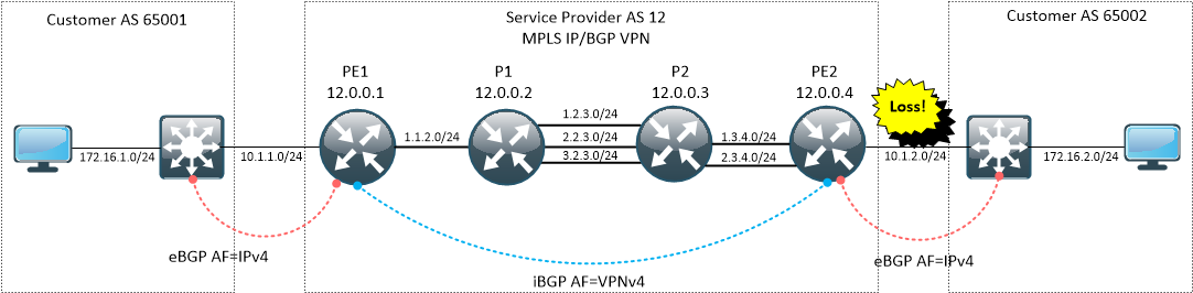
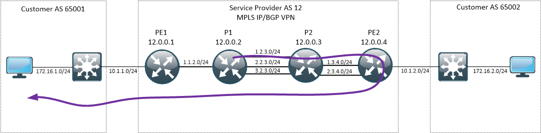
Our sample network
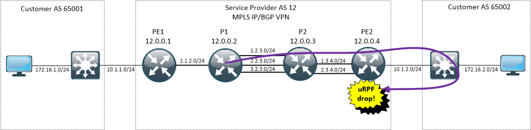
We will be working on a simple topology, consisting of Service Provider network and two customer sites. Connectivity between sites is built on top of MPLS IP/BGP VPN.
Scenario 1 - ASR920, per-prefix label allocation mode, no features
This is the simplest case possible. No additional features, just regular IP VPN with BGP as PE-CE routing protocol. I’m using ASR920 as P/PE routers with default label allocation mode which is per-prefix. This means that PE is allocating separate label for each prefix received from customer site.
Let’s do a quick verification first, especially paying attention to ingress/egress PE routers and LFIB.
CE1# sh ip route
<snip>
     172.16.0.0/24 is subnetted, 2 subnets
C       172.16.1.0 is directly connected, Vlan994
B       172.16.2.0 [20/0] via 10.1.1.1, 00:13:50
     10.0.0.0/24 is subnetted, 2 subnets
B       10.1.2.0 [20/0] via 10.1.1.1, 00:13:50
C       10.1.1.0 is directly connected, Vlan998
PE1#sh ip cef vrf A 172.16.2.0 detail
172.16.2.0/24, epoch 0, flags [rib defined all labels]
  recursive via 12.0.0.4 label 24
    nexthop 1.1.2.2 TenGigabitEthernet0/0/24 label 19-(local:21)
So, the label stack slapped on a packet destined to 172.16.2.0 will be [ 19 | 24 ].
On the other hand, from the perspective of egress PE, incoming packet with label 24 will have label stack stripped and be forwarded out BD10 interface towards next-hop 10.1.2.2. Router will use pre-built L2 rewrite string and no IP lookup is needed.
PE2#show mpls forwarding-table
Local      Outgoing   Prefix           Bytes Label   Outgoing   Next Hop
Label      Label      or Tunnel Id     Switched      interface
16         21         1.1.2.0/24       0             Gi0/0/0    1.3.4.3
           21         1.1.2.0/24       0             Gi0/0/1    2.3.4.3
17         Pop Label  1.2.3.0/24       0             Gi0/0/0    1.3.4.3
           Pop Label  1.2.3.0/24       0             Gi0/0/1    2.3.4.3
18         Pop Label  2.2.3.0/24       0             Gi0/0/0    1.3.4.3
           Pop Label  2.2.3.0/24       0             Gi0/0/1    2.3.4.3
19         Pop Label  3.2.3.0/24       0             Gi0/0/0    1.3.4.3
           Pop Label  3.2.3.0/24       0             Gi0/0/1    2.3.4.3
20         19         12.0.0.1/32      0             Gi0/0/0    1.3.4.3
           19         12.0.0.1/32      0             Gi0/0/1    2.3.4.3
21         22         12.0.0.2/32      0             Gi0/0/0    1.3.4.3
           22         12.0.0.2/32      0             Gi0/0/1    2.3.4.3
22         Pop Label  12.0.0.3/32      0             Gi0/0/0    1.3.4.3
           Pop Label  12.0.0.3/32      0             Gi0/0/1    2.3.4.3
23         No Label   10.1.2.0/24[V]   0             aggregate/A
24         No Label   172.16.2.0/24[V] 496584        BD10       10.1.2.2
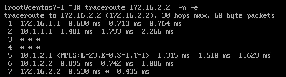
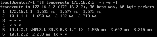
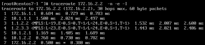
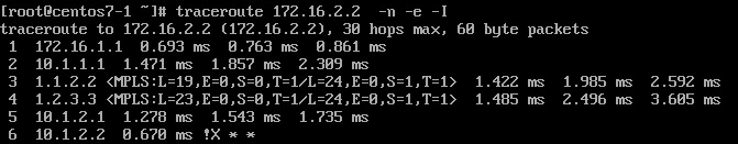
When we initiate traceroute from CE1 we receive the following output:
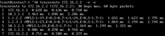
Let’s take a closer look to few first hops on the output above.
- Hop 1 – 172.16.1.1 - nothing extraordinary, regular reply from SW1
- Hop 2 – 10.1.1.1 - again, nothing extraordinary, regular reply from PE1
- Hop 3 – 1.1.2.2 - P1 receive a probe with TTL=1, so it gets punted to the RP.
*Feb 24 02:49:04.904: Adding 8 bytes of label stack
*Feb 24 02:49:04.905: MPLS: ICMP: time exceeded (time to live) sent to 172.16.1.2 (dest was 172.16.2.2) sent to src: 1.1.2.2 (origsrc: 1.1.2.2)intbl: 0 outtbl: 0 paktbl: 65535 outif: 0x76981024
What is different here from non-MPLS traceroute is that P1 can’t reply directly to the originator, because the label stack on the probe is not sufficient to identify the destination (172.16.1.2). The only thing it can do is to keep the packet on its original LSP hoping that the egress PE will know how to reach the probe source. Good way to think about this is to see MPLS IP/BGP VPN as a tunnel between two PEs. Devices in the middle are not aware of IP addressing scheme used in the VPN.
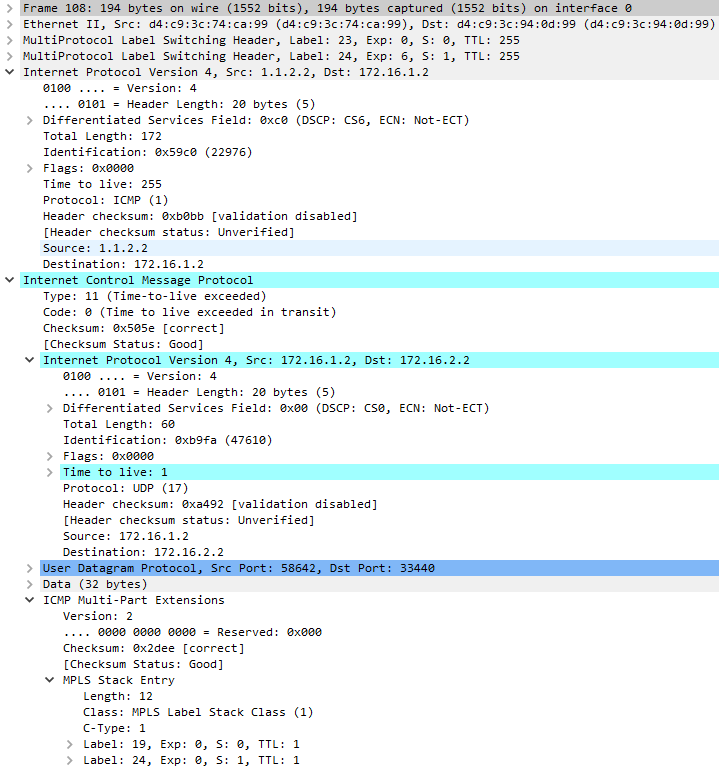
The reply is generated with src=1.1.2.2 (interface on which the probe was received), dst=172.16.1.2 and a label stack to keep the packet on its original LSP. The original probe packet came in with labels [24 | 19] and according to the FIB, should undergo label swap operation to [23 | 19]. Label stack placed on the generated reply packet will contain stack after swap operation and original label stack encoded as ICMP Multi-part extensions.
P1#show mpls forwarding-table  labels 19
Local      Outgoing   Prefix           Bytes Label   Outgoing   Next Hop
Label      Label      or Tunnel Id     Switched      interface
19         23         12.0.0.4/32      456657        Te0/0/25   1.2.3.3
           23         12.0.0.4/32      0             Te0/0/26   2.2.3.3
           23         12.0.0.4/32      0             Te0/0/27   3.2.3.3
Here is how the original packet arriving to P1 looks like.
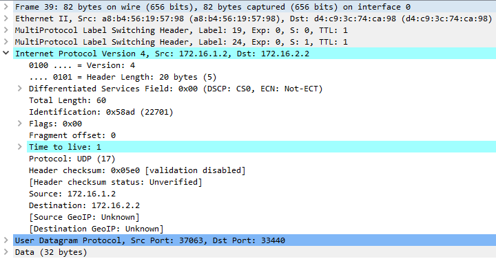
This is the reply packet generated by P1.
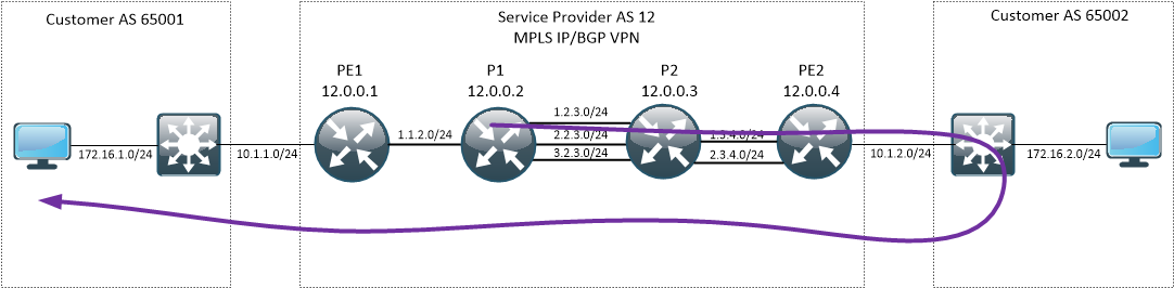
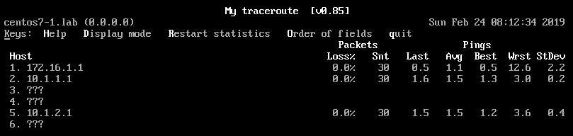
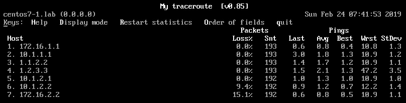
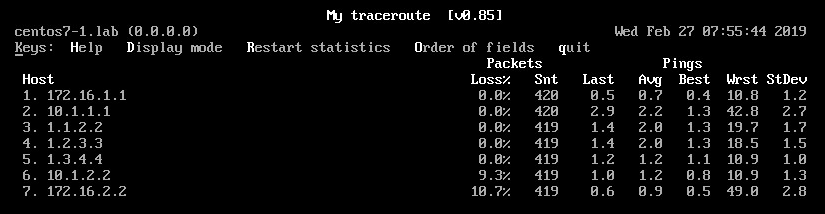
This has big impact on how our MTR output will look like, especially if we are measuring packet loss or latency. Imagine that the link between PE2-CE2 is faulty and is dropping packets like crazy.
How will the MTR from H1 point of view look like?
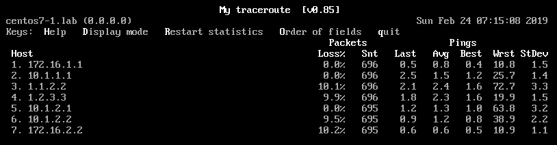
We see that that there is 10% packet loss on hop 3, 4, 6, 7. But why there is no loss reported on hop 5?
When PE2 receives a labeled packet with TTL=1, it is punted for software processing. What happens next depends on the platform and chosen label allocation mode. In our case, this is what we see on PE2:
*Feb 24 05:06:34.259: Adding 4 bytes of label stack
*Feb 24 05:06:34.259: MPLS: ICMP: time exceeded (time to live) sent to 172.16.1.2 (dest was 172.16.2.2) sent to src: 10.1.2.1 (origsrc: 1.3.4.4)intbl: 0 outtbl: 3 paktbl: 3 outif: 0x814AA01C
*Feb 24 05:06:34.259: IP: tableid=3, s=10.1.2.1 (local), d=172.16.1.2 (GigabitEthernet0/0/0), routed via FIB
So, replies generated by P1 and P2 have to cross PE-CE boundary and are affected by packet loss on PE-CE link. On the other hand, for packets that arrive to PE2 with TTL=1, the path is different – the packet does not have to leave the MPLS network.
This is important point to remember – traceroute showing packet loss somewhere in MPLS network does not have to mean loss inside SP network.
Scenario 1a - ASR920, per-prefix label allocation mode, unicast RPF strict mode
In this sub-scenario, we enable unicast RPF in strict mode on PE2 and we will see how does it impact our traceroute/mtr tools.
PE2# show bgp vpnv4 unicast all 172.16.2.0/24
BGP routing table entry for 12.0.0.4:1:172.16.2.0/24, version 43
Paths: (1 available, best #1, table A)
  Advertised to update-groups:
     6
  Refresh Epoch 1
  65002
    10.1.2.2 (via vrf A) from 10.1.2.2 (192.168.110.2)
      Origin incomplete, metric 0, localpref 100, valid, external, best
      Extended Community: RT:12:1
      mpls labels in/out 23/nolabel
      rx pathid: 0, tx pathid: 0x0
PE2(config-if)#ip verify unicast source reachable-via rx
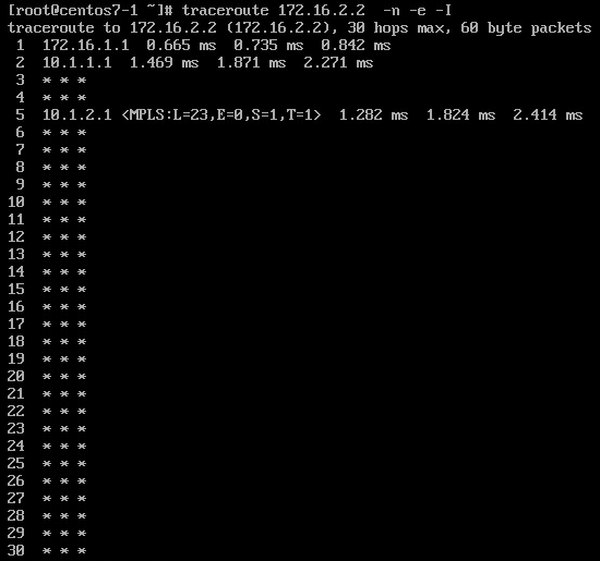
You already might suspect where I’m getting at. Since I showed in previous example that all replies generated by P routers have to leave the SP network to loop back towards the originator they most likely will be dropped at the perimeter when uRPF strict is on, because PE won’t have the route towards internal SP space via its customer.
Seeing "stars" in the traceroute output can mean that uRPF is in the game.
Scenario 1b - ASR920, per-prefix label allocation mode
In this sub-scenario, let's add an ACL on the customer device.
CE2#sh ip access-lists DROP_ICMP
Extended IP access list DROP_ICMP
    10 deny icmp any any (1 estimate match)
    20 permit ip any any (18 estimate matches)
CE2#
*Feb 24 07:48:19.414: ICMP: dst (172.16.2.2) administratively prohibited unreachable sent to 172.16.1.2
*Feb 24 07:49:47.954: ICMP: time exceeded (time to live) sent to 172.16.1.2 (dest was 172.16.2.2)
*Feb 24 07:49:47.954: ICMP: time exceeded (time to live) sent to 172.16.1.2 (dest was 172.16.2.2)
*Feb 24 07:49:47.954: ICMP: time exceeded (time to live) sent to 172.16.1.2 (dest was 172.16.2.2)
*Feb 24 07:51:52.230: ICMP: dst (172.16.2.2) administratively prohibited unreachable sent to 172.16.1.2
Traceroute from H1 point of view should reveal that ICMP packets are filtered at customer permeter.
When we slightly modify the configuration of CE2 by setting
CE2(config-if)#no ip unreachables
traceroute will not end.
Scenario 2 - ASR920, per-VRF label allocation mode, no features
Let's slightly modify the scenario and change the label allocation mode on PE2 to per-VRF.
PE2(config)#mpls label mode all-vrfs protocol all-afs per-vrf
PE2# show bgp vpnv4 unicast all 172.16.2.0/24
BGP routing table entry for 12.0.0.4:1:172.16.2.0/24, version 41
Paths: (1 available, best #1, table A)
  Advertised to update-groups:
     6
  Refresh Epoch 1
  65002
    10.1.2.2 (via vrf A) from 10.1.2.2 (192.168.110.2)
      Origin incomplete, metric 0, localpref 100, valid, external, best
      Extended Community: RT:12:1
      mpls labels in/out IPv4 VRF Aggr:18/nolabel
      rx pathid: 0, tx pathid: 0x0
PE2#show mpls forwarding-table labels 18 detail
Local      Outgoing   Prefix           Bytes Label   Outgoing   Next Hop
Label      Label      or Tunnel Id     Switched      interface
18         Pop Label  IPv4 VRF[V]      0             aggregate/A
        MAC/Encaps=0/0, MRU=0, Label Stack{}
        VPN route: A
        No output feature configured
We see that for incoming packets with label 18, the router need to perform an additional IP lookup – there is no next-hop and L2 rewrite string information.
This does not change the traceroute logic, but does change the path of the probes, which do not have to leave the servic provider boundary. This has massive impact on MTR results when we consider our lossy link scenario again.
The MTR looks like now completely different and is much closer to what would we expect. It shows the loss precisely at the point where the problem is.
Scenario 2a - ASR920, per-VRF label allocation mode, uRPF strict
We enable uRPF strict on PE2:
PE2(config-if)#ip verify unicast source reachable-via rx
It turns out that per-VRF label allocation fixes gaps in our traceroute we previously had, because now the replies generated by P routers are looping back on PE2. This is because PE2 has to make this additional IP lookup, so when it gets a reply generated by P1 (src=1.1.2.2, dst=172.16.1.1, proto=ICMP) it doesn’t cross the PE-CE boundary.It turns out that per-VRF label allocation fixes gaps in our traceroute we previously had, because now the replies generated by P routers are looping back on PE2. This is because PE2 has to make this additional IP lookup, so when it gets a reply generated by P1 (src=1.1.2.2, dst=172.16.1.1, proto=ICMP) it doesn’t cross the PE-CE boundary.
PE2#show mpls forwarding-table
Local      Outgoing   Prefix           Bytes Label   Outgoing   Next Hop
Label      Label      or Tunnel Id     Switched      interface
16         21         1.1.2.0/24       0             Gi0/0/0    1.3.4.3
           21         1.1.2.0/24       0             Gi0/0/1    2.3.4.3
17         Pop Label  1.2.3.0/24       0             Gi0/0/0    1.3.4.3
           Pop Label  1.2.3.0/24       0             Gi0/0/1    2.3.4.3
20         19         12.0.0.1/32      0             Gi0/0/0    1.3.4.3
           19         12.0.0.1/32      0             Gi0/0/1    2.3.4.3
21         22         12.0.0.2/32      0             Gi0/0/0    1.3.4.3
           22         12.0.0.2/32      0             Gi0/0/1    2.3.4.3
22         Pop Label  12.0.0.3/32      0             Gi0/0/0    1.3.4.3
           Pop Label  12.0.0.3/32      0             Gi0/0/1    2.3.4.3
24         Pop Label  IPv4 VRF[V]      18690         aggregate/A
Scenario 2b - ASR920, per-VRF label allocation mode, ACL
CE2(config-if)#int vlan 997
CE2(config-if)#ip access-group DROP_ICMP in
CE2(config-if)#end
SW1#
*Feb 24 08:19:02.026: %SYS-5-CONFIG_I: Configured from console by console
*Feb 24 08:19:24.638: ICMP: dst (172.16.2.2) administratively prohibited unreachable sent to 172.16.1.2
If we add no unreachables
SW1(config)#int vlan 997
SW1(config-if)#no ip un
SW1(config-if)#no ip unr
SW1(config-if)#no ip unreachables
SW1(config-if)#

Scenario 3 - ASR9000, per-prefix label allocation mode, no features
In this scenario, I’ve swapped PE2 hardware platform from ASR920 to ASR9001 running IOS XR 6.4.2.
Label allocation mode is per-prefix by default.
RP/0/RSP0/CPU0:PE2#show bgp vrf A labels
Wed Feb 27 13:36:52.910 CET
BGP VRF A, state: Active
BGP Route Distinguisher: 12.0.0.4:1
VRF ID: 0x60000003
BGP router identifier 12.0.0.4, local AS number 12
Non-stop routing is enabled
BGP table state: Active
Table ID: 0xe0000012   RD version: 77
BGP main routing table version 77
BGP NSR Initial initsync version 1 (Reached)
BGP NSR/ISSU Sync-Group versions 0/0

Status codes: s suppressed, d damped, h history, * valid, > best
              i - internal, r RIB-failure, S stale, N Nexthop-discard
Origin codes: i - IGP, e - EGP, ? - incomplete
   Network            Next Hop        Rcvd Label      Local Label
Route Distinguisher: 12.0.0.4:1 (default for vrf A)
*>i10.1.1.0/24        12.0.0.1        18              nolabel
*> 10.1.2.0/24        0.0.0.0         nolabel         24007
*                     10.1.2.2        nolabel         24007
*>i172.16.1.0/24      12.0.0.1        19              nolabel
*> 172.16.2.0/24      10.1.2.2        nolabel         24005

Processed 4 prefixes, 5 paths
RP/0/RSP0/CPU0:ASR9k-SPARE#show mpls forwarding
Wed Feb 27 13:41:08.211 CET
Local  Outgoing    Prefix             Outgoing     Next Hop        Bytes
Label  Label       or ID              Interface                    Switched
------ ----------- ------------------ ------------ --------------- ------------
24000  19          12.0.0.1/32        Gi0/0/1/0    1.3.4.3         0
       19          12.0.0.1/32        Gi0/0/1/1    2.3.4.3         24644
24001  22          12.0.0.2/32        Gi0/0/1/0    1.3.4.3         0
       22          12.0.0.2/32        Gi0/0/1/1    2.3.4.3         0
24002  Pop         12.0.0.3/32        Gi0/0/1/0    1.3.4.3         0
       Pop         12.0.0.3/32        Gi0/0/1/1    2.3.4.3         686
24003  21          1.1.2.0/24         Gi0/0/1/0    1.3.4.3         0
       21          1.1.2.0/24         Gi0/0/1/1    2.3.4.3         0
24004  Pop         1.2.3.0/24         Gi0/0/1/0    1.3.4.3         0
       Pop         1.2.3.0/24         Gi0/0/1/1    2.3.4.3         0
24005  Unlabelled  172.16.2.0/24[V]   Gi0/0/1/2.999 10.1.2.2        0
24007  Aggregate   A: Per-VRF Aggr[V] A                            0
RP/0/RSP0/CPU0:PE2#show mpls forwarding labels 24005 detail location 0/0/CPU0
Wed Feb 27 13:44:06.437 CET
Local  Outgoing    Prefix             Outgoing     Next Hop        Bytes
Label  Label       or ID              Interface                    Switched
------ ----------- ------------------ ------------ --------------- ------------
24005  Unlabelled  172.16.2.0/24[V]   Gi0/0/1/2.999 10.1.2.2        0
     Updated: Feb 27 13:40:27.015
     Path Flags: 0x6020 [  EXT ]
     Version: 94, Priority: 3
     Label Stack (Top -> Bottom): { Unlabelled }
     NHID: 0x0, Encap-ID: N/A, Path idx: 0, Backup path idx: 0, Weight: 0
     MAC/Encaps: 18/18, MTU: 1500
     Outgoing Interface: GigabitEthernet0/0/1/2.999 (ifhandle 0x04000bc0)
     Packets Switched: 0
RP/0/RSP0/CPU0:PE2#LC/0/0/CPU0:Feb 27 14:03:01.678 CET: ipv4_io[244]: Punt received for ICMP error: type: 0, subtype: 0
LC/0/0/CPU0:Feb 27 14:03:01.678 CET: ipv4_io[244]: ipv4_process_icmppunt: Punt received src: 172.16.1.2, dst: 172.16.2.2, frag_off:0x0
LC/0/0/CPU0:Feb 27 14:03:01.678 CET: ipv4_io[244]: ipv4_process_icmppunt: Entering mpls preroute pak rcvd
LC/0/0/CPU0:Feb 27 14:03:01.678 CET: ipv4_io[244]: pak proto num is 1
LC/0/0/CPU0:Feb 27 14:03:01.678 CET: ipv4_io[244]: Punt reason: TTL Expired
LC/0/0/CPU0:Feb 27 14:03:01.678 CET: ipv4_io[244]: normal pak: type: 11, code: 0, mtu: 0, df: 0, ttl: 1
LC/0/0/CPU0:Feb 27 14:03:01.678 CET: ipv4_io[244]: mpls_offset: 0 ip_offset: 4
LC/0/0/CPU0:Feb 27 14:03:01.678 CET: ipv4_io[244]: ip_lib_mpls_ipv4_rx_punt_pak: badpak ip hdr: src=<172.16.1.2>,dst=<172.16.2.2>,frag_off=0x0
LC/0/0/CPU0:Feb 27 14:03:01.678 CET: ipv4_io[244]: Creating icmp time exceed pkt
LC/0/0/CPU0:Feb 27 14:03:01.679 CET: ipv4_io[244]: icmp time exceed pkt i/f 0x40002c0
LC/0/0/CPU0:Feb 27 14:03:01.679 CET: ipv4_io[244]: orig ssz: 64,ip_offset: 4,icmp_size: 168,stacksz: 4, mpls_off: 0
LC/0/0/CPU0:Feb 27 14:03:01.679 CET: ipv4_io[244]: pak_client_add_tail 108
LC/0/0/CPU0:Feb 27 14:03:01.679 CET: ipv4_io[244]: ip_lib_mpls_ipv4_rx_punt_pak: ip_icmp hdr: src=<1.3.4.4>,dst=<172.16.1.2>,frag_off=0x0
LC/0/0/CPU0:Feb 27 14:03:01.679 CET: ipv4_io[244]: Freeing icmp pkt
LC/0/0/CPU0:Feb 27 14:03:01.679 CET: ipv4_io[244]: ip_lib_mpls_ipv4_rx_punt_pak: sending icmp packet to: src=<1.3.4.4>,dst=<172.16.1.2>
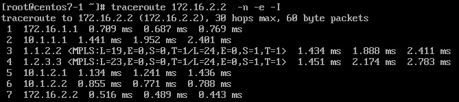
When we source traceroute from H1, we see
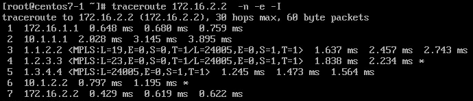
Although there is no difference to the output from Scenario1, there is a difference in path which packet reply generated on PE2 follows. This will become obvious when we consider our “lossy link” scenario once again.
This is how MTR looks like assuming we have packet drops on PE2-CE2 link.
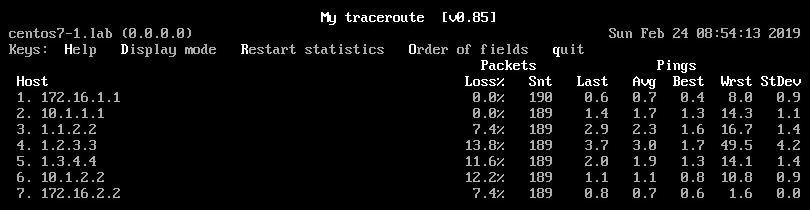
Now we see loss on hops 3-7. Previously, we did not have loss on hop 5 (PE2). My best guess is that the difference lies in platform differences.
- ASR920 generates reply and despite per-prefix label allocation mode it use FIB lookup to forward the packet, so the packet doesn’t hit PE-CE link
- ASR9k generates reply and use LFIB lookup to forward the packet, so the packet does hit PE-CE link
Scenario 4 - ASR9000, per-VRF label allocation mode, no features
In this scenario, I’m switching label allocation mode on PE2 to per-VRF, forcing additional IP lookup on the egress PE. We see that Outgoing label is “aggregate” now.
RP/0/RSP0/CPU0:PE2#show mpls forwarding
Wed Feb 27 13:27:22.337 CET
Local  Outgoing    Prefix             Outgoing     Next Hop        Bytes
Label  Label       or ID              Interface                    Switched
------ ----------- ------------------ ------------ --------------- ------------
24000  19          12.0.0.1/32        Gi0/0/1/0    1.3.4.3         401696
       19          12.0.0.1/32        Gi0/0/1/1    2.3.4.3         680463
24001  22          12.0.0.2/32        Gi0/0/1/0    1.3.4.3         0
       22          12.0.0.2/32        Gi0/0/1/1    2.3.4.3         0
24002  Pop         12.0.0.3/32        Gi0/0/1/0    1.3.4.3         0
       Pop         12.0.0.3/32        Gi0/0/1/1    2.3.4.3         474242
24003  21          1.1.2.0/24         Gi0/0/1/0    1.3.4.3         0
       21          1.1.2.0/24         Gi0/0/1/1    2.3.4.3         0
24004  Pop         1.2.3.0/24         Gi0/0/1/0    1.3.4.3         0
       Pop         1.2.3.0/24         Gi0/0/1/1    2.3.4.3         0
24007  Aggregate   A: Per-VRF Aggr[V] A                            506836
RP/0/RSP0/CPU0:ASR9k-SPARE#show mpls forwarding labels 24007 detail
Wed Feb 27 13:46:59.795 CET
Local  Outgoing    Prefix             Outgoing     Next Hop        Bytes
Label  Label       or ID              Interface                    Switched
------ ----------- ------------------ ------------ --------------- ------------
24007  Aggregate   A: Per-VRF Aggr[V] A                            1260
     Updated: Feb 21 17:04:19.156
     Label Stack (Top -> Bottom): { }
     MAC/Encaps: 0/0, MTU: 0
     Packets Switched: 15
This means that the router is forced to perform an IP lookup in respective VRF.
RP/0/RSP0/CPU0:PE2#LC/0/0/CPU0:Feb 27 14:01:31.370 CET: ipv4_io[244]: Punt received for ICMP error: type: 11, subtype: 0
LC/0/0/CPU0:Feb 27 14:01:31.370 CET: ipv4_io[244]: ipv4_process_icmppunt: Punt received src: 172.16.1.2, dst: 172.16.2.2, frag_off:0x0
LC/0/0/CPU0:Feb 27 14:01:31.370 CET: ipv4_io[244]: ipv4_icmp_error_trigger: type: 11, code: 0
LC/0/0/CPU0:Feb 27 14:01:31.370 CET: ipv4_io[244]: ipv4_icmp_error_trigger : interf addr is 1.3.4.4, if hdl 0x40002c0 idb exists: 1
LC/0/0/CPU0:Feb 27 14:01:31.370 CET: ipv4_io[244]: ipv4_icmp_error_make : type : 11, code: 0
LC/0/0/CPU0:Feb 27 14:01:31.371 CET: ipv4_io[244]: Sending ICMP timeout to 172.16.1.2
LC/0/0/CPU0:Feb 27 14:01:31.371 CET: ipv4_io[244]: ipv4 icmp common sendnet: Sending pak(0xddc77ec7) to netio, tid: 4
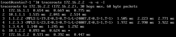
Above confirms that the packet "loop backs" towards the probe source on PE1, without hitting PE-CE link.
Conclusion
- Behavior of traceroute in MPLS networks can be influenced by a number of factors, like label allocation mode, configured features (uRPF) and hardware platform
- Traceroute/MTR outputs are closest to the truth when egress PE is forced to perform IP lookup
- Packet loss in the SP network shown on MTR outputs can mean problems outside SP network, or maybe no problems at all (because of Control Plane Protection, ICMP rate limiting)
Comments
comments powered by Disqus