This is one of the oldest methods of implementing multicast in Service Providers core. Quite popular, but unfortunately has some serious limitations.
We will see the operation of Draft-Rosen deployment model in practice by building sample lab topology and looking how particular pieces of technology fit together. Let’s look at the topology we will be building.
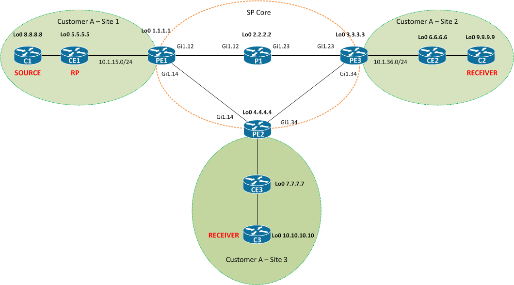
We have a very simple Service Provider core consisting of routers PE1, PE2, PE3 and P1. Also, there is Customer A which want to have MPLS/IP VPN with the ability to stream multicast feed from Site 1 to receivers located in Site 2 and Site 3. This is extremely simple example of multicast application, but is enough to understand basic building blocks of Draft-Rosen mGRE.
Background information
- Customer is running PIM-SM, RP is defined statically
- PE1, PE2, PE3 have VRF
Customer_Aconfigured - All protocols required for MPLS/IP VPNs are configured (OSPF, LDP, MP-BGP)
- Basic unicast reachability between all customer sites is established
- OSPF is used as PE-CE routing protocol
How does it work?
From a high level perspective, customer doesn’t care what mechanisms runs inside SP network. The ultimate goal is to have the ability for remote sites to signal the need of particular multicast stream by means of standard protocol (PIM) and have that stream delivered.
To achieve the above goal, multiple steps have to occur:
- CE2 has to signal PE3 the desire to receive the multicast traffic via PIM Join message
- PE3 has to propagate this information across SP cloud to the PE connected to the site that contains the RP
- PE1 has to propagate this information down to RP, also via PIM Join message
Steps 1 and 2 occur inside mVPN domain, while step 3 occur inside SP network.
Because PE3 knows the unicast RP address, it might seem reasonable to forward the PIM Join towards PE1 only, but for instance, what if the customer had used PIM BSR to distribute RP information?
In Draft-Rosen mGRE implementation, control-plane traffic inside mVPN is always propagated to all PE routers that participate in that mVPN.
According to RFC 6037
An SP determines whether a particular VPN is multicast-enabled. If it is, it corresponds to a "Multicast Domain". A PE that attaches to a particular multicast-enabled VPN is said to belong to the correspnding Multicast Domain. For each Multicast Domain, there is a default multicast distribution tree ("MDT") through the backbone, connecting ALL of the PEs that belong to that Multicast Domain.
In a departure from the usual multicast tree distribution procedures, the Default MDT for a Multicast Domain is constructed automatically as the PEs in the domain come up. Construction of the Default MDT does not depend on the existence of multicast traffic in the domain; it will exist before any such multicast traffic is seen. Default MDTs correspond to the Multidirectional Inclusive P-Multicast Service Interfaces ("MI-PMSIs") of [MVPN]
Okay, so we know that PIM Join coming from PE3 is supposed to get to PE1 and PE2, because they are part of that mVPN. How does this happen?
In order to carry the PIM information among the PE routers PIM adjacencies are set up. It’s important to note that these PIM adjacencies are created per-VPN.
To carry these customers’ PIM messages Tunnel interfaces are automatically created on PE routers. Their purpose is to encapsulate customer multicast traffic into GRE and another multicast envelope. These tunnels are called the Multicast Distribution Tree, which conceptually create abstraction of a LAN to which all the PEs belonging to a mVPN are attached. If there are N PE routers, N point-to-multipoint multicast trees are constructed. Each PE router will have N-1 tunnels brought up. In my understanding, the tunnel interface is a “gateway” to encapsulate customer’s multicast traffic into GRE + another IP header which can traverse SP core.
This is how it looks like if we display PIM neighbors of PE1 inside VRF A.
PE1#sh ip pim vrf A neighbor
PIM Neighbor Table
Mode: B - Bidir Capable, DR - Designated Router, N - Default DR Priority,
      P - Proxy Capable, S - State Refresh Capable, G - GenID Capable,
      L - DR Load-balancing Capable
Neighbor          Interface                Uptime/Expires    Ver   DR
Address                                                            Prio/Mode
10.1.15.5         GigabitEthernet1.15      00:26:12/00:01:39 v2    1 / DR S P G
4.4.4.4           Tunnel0                  00:25:08/00:01:39 v2    1 / DR S P G
3.3.3.3           Tunnel0                  00:25:08/00:01:41 v2    1 / S P G
This brings us to another question - how does the router know how to encapsulate the customer traffic? And the answer is – because you have configured it.
 rd 1:1
 mdt default 232.0.0.1
 route-target export 1:1
 route-target import 1:1
When configuring VRF on PE router, you have to define multicast group that is going to be used to encapsulate customer’s traffic. The group has to be the same on every PE router that belong to that particular mVPN. Also, this is how a PE router can identify incoming multicast traffic and direct it into correct VRF. So at this point, we know that PIM Join is being encapsulated into GRE and another IP multicast packet destined to 232.0.0.1. But how does the PE3 know where to send it? This is where another PIM instance comes into play. In Draft-Rosen mGRE, two levels of PIM are used: * C-instance to build tree inside each customer's VPN * P-instance to build tree (MDT) in the core
Inside SP networks we have quite few options:
- PIM ASM
- PIM SSM
- BiDir PIM
Depending on our choice, there are additional factors to consider. When using SSM, PE3 would need to know the (S,G) pair. G is already known because you have configured it, but what about S? The answer is PE3 doesn’t have a clue about other PE routers. There has to be an external mechanism to discover other PE routers and in case of Draft-Rosen it is BGP AF MDT.
In case of ASM the PE routers are configured with RP address, so they can build (*,G) state and automatically join (S,G) tree. No BGP needed here.
Look from design perspective
As of today, I don’t think that Draft-Rosen mGRE should be used in any greenfield MPLS deployment. Mainly because of these drawbacks:
- Lack of IPv6 support
- Have to run another protocol in the core (PIM)
- Lack of FRR mechanisms
- Large amount of state in SP network
Comments
comments powered by Disqus